FarSounder's Acoustic Test Tank Facility
We’ve just completed the finishing touches on a brand new test tank facility in our main office. Our primary motivation for building this new facility was to increase our production productivity, since every sonar unit we produce is tank tested and calibrated before shipment. Our previous tank was located in a warehouse about 3 miles (~5 km) from our offices. Compared to our old tank, the new one is larger, deeper, and WAY more convenient.

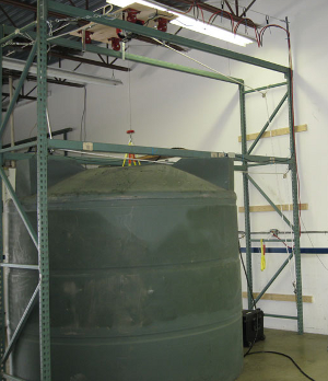
FarSounder's acoustic test tank with calibration electronics workstation.
A Transducer Module is being lowered into FarSounder's previous tank for calibration. That tank was built from a prefabricated, molded plastic tank.
Tank Design and Construction
When considering the design of our new tank, we had four primary design constraints:
Room size
Minimum dimensions needed for calibration
Ease of Transducer Module production testing and calibration
Ease of construction
The room size limitation was quite fixed, since the tank needed to fit in an existing engineering space. The primary limitation in size is the ceiling height. We only have a little over 10 feet (3.3 m) to the cement deck of the floor above. Since the tank was being built in an existing building, and there are no large access doors, digging into the floor was not realistic. This means we need to be clever about how we get the Transducer Module into the tank.
It is easy for us to specify the minimum dimensions needed for calibration. Our previous tank was constructed from a 2700 gallon cylindrical plastic tank, and that worked great for all of our production measurements. That tank was about 85 inches in diameter, and the water was about 72 inches deep. So we knew that we wanted a tank that was at least that big.
Our new tank is in the same office suite as our assembly space. This means that a Transducer Module ready for calibration can easily be carted to the tank room. We use a hoist on a boom arm to lift the Transducer Module from a cart or shipping case up above the top deck of the tank. The boom arm then pivots to position the Transducer Module directly over the center of the tank. We have a calibrated source projector pre-located in the tank. A pair of chocks align the Transducer Module precisely when the Transducer Module is lowered into the water. In order to facilitate the measurement process, we have dedicated test electronics permanently set up and ready to go.

The design concept for FarSounder's new tank consists of a wooden frame built with 2x6 lumber with decking on top.
With the above limitations/considerations, we set about to design a tank that would be simple to fabricate. We decided on a freestanding structure based on 10 foot long 2x6 lumber. Before assembly, three small holes were drilled through each board along the centerline: one at 2.75 inches from each end and one in the middle. By laying the lumber on its side and alternating front/back then side/side, we built interleaved wooden panels for each side. In each corner, a threaded rod was run through the holes to align all the boards in each wall. Threaded rods were also run through the holes in the middle of the boards, with a small spacer between each layer of 2x6 boards.

The wooden wall frame including the window on the front of the tank can be seen while the tank was under construction.
The inside of the walls and the floor were lined with plywood. A pool liner was then installed on the plywood walls allowing for 78” inches of water depth. Joists were run across the top of the tank to allow for plywood decking. In the center of the deck is a 24” x 24” access hatch where we deploy the Transducer Module under test.
To make the tank a little nicer looking and more user friendly, a viewing port was added into the front wall, and the front outside wall was covered in plywood. Lights inside the tank were added by cutting small access holes in the deck and installing the lights from above. The finished result is a test tank that not only looks great, but also is configured to make our production calibration measurements quick and easy.
The Calibration Process

The angular response of a test signal without any calibration applied to an array.
The Transducer Modules in our current products have between about 50 and 200 receiver elements. Strict manufacturing processes ensure that each of these elements are very similar to each other. However, even transducers manufactured under the most rigid processes will still vary slightly from element to element. This variation is normal and can be easily accounted for in our software as long as the variations are measured precisely. This is where our production calibration comes into play.

The angular response of a test signal after applying calibration to an array.
We use a calibrated acoustic source to transmit a known signal into all of the receiver elements simultaneously. Using the data collection electronics housed inside the Transducer Module, we are able to digitize the reference signal, determine the source location relative to the receiver array, and measure the relative amplitude and phase of the incoming signal for each element. Since the path from the calibrated source to each receiver element is slightly different, we need to remove the impact of the path variations to each element. Once we normalize for the path differences, we are left with the amplitude and phase variations for each receiver channel including the transducer element, pre-amp, and analog signal conditioning electronics.
Our Transducer Modules do not operate at a single frequency. Rather, they operate across a band of frequencies. Therefore, we perform these measurements across their entire frequency range. At each frequency, we collect data from multiple pings so that we can perform ping to ping averaging and other statistical processes. This translates to collecting hundreds of pings per Transducer Module per calibration. This may sound like a lot of work. However, we’ve written some custom calibration software tools which automate the process. The output of this tool is a series of plots we use for quality control purposes and a calibration file which gets attributed to a specific Transducer Module serial number. One might compare this calibration file for our sonars to a prescription for a pair of glasses. The whole process takes about 15 minutes per unit.
Future Testing
FarSounder’s previous test tank was sized at about the minimum size needed for frequent production measurements. For less frequent R&D measurements needing a larger tank, renting time at a larger acoustic test tank facility was always needed. Since our new tank is considerably larger than our previous one, it will now be possible to perform locally some of the R&D measurements that required renting an off-site tank. Bringing these measurements to an in-house facility will also greatly improve productivity in those areas. Because the deck is made from plywood, it can always be reconfigured with additional access hatches as needed.